OpenBuildings™ Station Designer Help

Place Joist Girders

Helps to automate joist girder modeling by utilizing standard sizes and series configurations. The joist girder tool supports the creation and modification of joist girders with parallel chords. There are four panel configurations or series (G, VG, BG and SP) providing different arrangements of diagonal and vertical web members to chose from.

Accessed from:


  • Ribbon: Building Design > Structural > Place Structural Elements > Trusses split button > Place Joist Girders


Note: A joist girder is a primary structural load carrying member with an open web system designed as a simple span supporting equally spaced concentrated loads of a floor or roof system acting at the panel points of the joist girder.

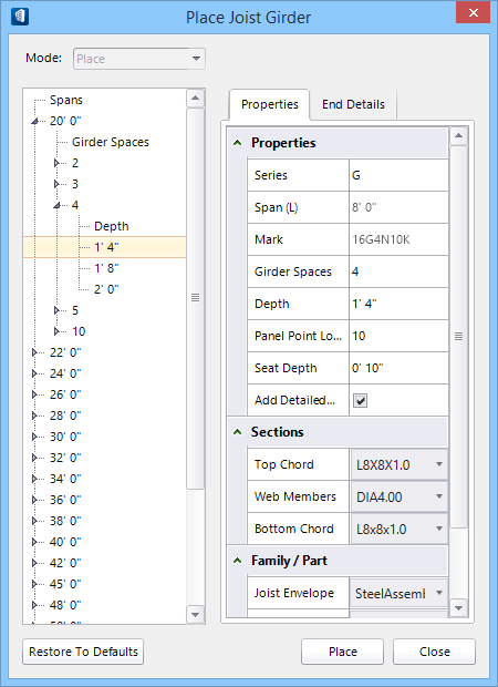
Place Joist Girder dialog

Initially, selecting opens a preliminary dialog which governs the main tool settings window.


SettingDescription
Mode Select the placement or modification modes used for designing joist girders. Selections made here determine the prompts that guide you through the tool modes.
Place One joist girder assembly is placed as a compound cell along the selected span. Spans are specified using data points between structural members or other elements.
Modify Previously placed joist girders are modified in the Change Girder Attributes by selecting this option and then selecting the joist girder. Modify seat heights, series and section definitions for example.
Note: Mode is not editable once selected for a given joist girder. It is disabled in the Place Joist Girder and in the Change Girder Attributes dialogs

Properties tab

SettingDescription
Spans Tree Displays default choices of girder spaces and joist depths for spans equal to or greater than the distance defined by the placement mode datapoints. Choices are based on industry standard joist girder tables encoded in JoistGirderSettings.xml located in the active dataset folders.

Each Span in the tree contains a set of Girder Spaces and Depths for that span. Clicking Span expands the tree to display all the Girder Spaces available for that span. Similarly, clicking individual Girder Spaces entries expands the tree further revealing the available joist Depths. Selecting a depth in the tree automatically sets the property values.

Note: Choices offered in the Spans Tree are common configurations. They can be overwritten by entering different property values.
Properties Lists and sets series properties.
  • Series — Controls the geometry of the diagonal and vertical members in the joist girder assemblies with respect to panel points. Panel points are defined as the location where one or more web members intersect the top or bottom chords of a joist girder. The Series choices are:


    Available Joist Girder Series (1 through 4). Vertical arrows represent Panel Points (3). Horizontal arrows represent girder spaces (4).

    1. G - Panel points are located at the intersections of the diagonal web members.
    2. VG - Panel points are located on the vertical web member positions.
    3. BG - Panel points are located on both intersections of diagonal web members and on the vertical web member positions.
    4. SP - Panel points are located at the intersections of the diagonal web members. The SP series is similar to the G series but with an additional vertical web member in the first and last girder spaces.
  • Span (L) - Displays the span selected from the Spans Tree. The field is filled in after the joist Depth is selected.
  • Mark - Displays the standard designation for the joist girder based on the selections made in the Spans Tree.
    Note: Editable properties can be modified by keying in new values. The naming convention's syntax structure is:<Depth><Series><Girder Spaces>N<Panel Point Load>K Where: For example: 48G8N8.8K denotes a G series joist girder with a depth of 48 units. The girder has 8 spaces with a load of 8.8 units of force at each panel point.
    • Depth – Joist girder depth in active working units.
    • Series – G, VG, BG or SP
    • Girder Spaces – Number of panels.
    • Panel Point Load – Load on each panel point.
  • Girder Spaces — Used to select the number of spaces in the joist girder.
  • Depth — Used to key in joist girder depth values.
  • Panel Point Load (K) — Used to key in panel point load values.
  • Seat Depth — Used to select the depth of the seats. Each seat on the joist girder has the same seat depth.
  • Add Detailed Members — When on, top and bottom chords, web members and seats are modeled in full detail. When off, only the joist envelope is modeled.
Sections Contains settings that define the section data for the joist girder you are modeling. These settings determine section definitions used for the individual components that comprise the joist girder assembly.
  • Top Chord - Select/browse for the section definition to be used for the top chord members.
  • Web Members - Select/browse for the section definition to be used for the web members.
  • Bottom Chord - Select/browse for the section definition to be used for the bottom chord members.
Click the value field to open a section picker where the Structural section data is set.
Family / Part Sets the part/family values from the combo selection box opened by clicking the selection menu next to the field. Determines family/part data used for the individual components that comprise the joist girder assembly.
  • Joist Envelope — Select the family and part for the joist envelope.
  • Top Chord — Select the family and part for the top chord.
  • Web Members — Select the family and part for the web members.
  • Bottom Chord — Select the family and part for the bottom chord.
Reset to Defaults All the recent changes to settings are restored to default settings. Momentarily turned bold-faced values thus revert back to normal.
Place Places the joist girder after both tab's settings are defined.
Close Closes the dialog.
Key-in: [BENTLEY.BUILDING.STRUCTURAL.JOISTGIRDERTOOL] STRUCTURALTOOLS LOAD JOISTGIRDER